

Hello again,
This post
relates to a tool I saw when I was in the consumer electronics appliance service
sector decades ago. It was elegant with a posh steel case with various lit
buttons and a cute little CRT tube on the left. We techs were told that it's
for checking components characteristics. I thought it was a small scope for
outdoor jobs. I can't remember the brand but the face panel looked approximate
to a Polar T series Fault Locator or Huntron Tracker series.

In summer (meaning
when it isn't raining) of 93/94, we were called for a demonstration of the aforementioned
tool by a visiting sales rep of a TMI company. I was intrigued by the demo, especially
amazed when he tested capacitors. Depending on the capacitor value it would
display a variety of round to elliptical figures/patterns. I never knew such a fancy
test could be done on a CRT based equipment. I knew from school about checking
polarized caps with an analog multimeter. Nothing complex but observing the
needle go up and down to indicate a pass but with that fancy tool, it looked
more attractive and intelligently presented.

Long story
short, our company acquired the Component Debugger (the sales rep called it).
Quite awkward considering we've been using that connotation prior for everyone
and everything in our dept. You know, like this bugger, that bugger, you
bugger, in a joking kind of a way. Anyway soon after, I never saw any of us use
the Component Debugger for trouble shooting. To be honest, at the time none of
us understood how aiding it could be if it came to it. We rather had someone
else have a go at it then perhaps teach us how at the end of the day. It's in
our eastern culture, you know, you first, no you first, no by all means please
etc.

The fact was we
were all lazy and busy with incoming repairs. We were too comfortable with the presto
digits of the DMM, dry tenors of the AF Gen, and revealing show on the Oscilloscope.
Maybe we were too polite to the outsider (salesman) during the demo that we
just nodded concurring the Component Debugger prominence foregoing procurement.
Our Assistant Service Manager did one time admit buyer’s remorse. I’m sure he
got questioned by people upstairs. It was not his fault. The salesman were
indeed resounding in his words gymnastics and jargons. What we should have done
was put both him and his debugger in a room filled of faulty electronics. Fix 5
sets with it then we'll buy and let you go or we'll beat the bugger out of you.
Hehe.

Good thing it
was only one unit, not 18 for each of us or I guarantee we’d gone to his office
after work and beat every buggers in the hind quarters! That little debugger must’ve
cost an arm and leg back then I’m sure. No joke!

It was only
after I'd stumbled upon several videos on YouTube that I really understood what
an invaluable test gear we had back then. It may not ever replace all I've
mentioned but one more test gear is never too many. The more assessment types could
be done, the more definite the analysis will be.
I am also
admitting here that it took me 25 years to figure out (vaguely) what the
Component Debugger was. What an idiot this writer is. Hehe.

After coming to
know how expensive a dedicated Curve Tracer unit is on eBay, I decided to make
one. A science fair version more or less embezzled from old electronic magazines
with countless of designs online. Fairly simple but I am adding my own touches
to make it snobbish and untraceable.
Initially it must be AC powered (115V or 230V), neat, slender and trifling enough to carry or ship off. I've always liked Boss pedals so I borrowed the DD-2 theme (reverse). White font/Blue background on both front/rear panel.

Due to how
minimal components were required, I could select them to be as high street as I
could fork it. For longevity reason. I
designed the circuit using an online PCB software that associates with a
renowned PCB fabrication company in China. The website is well-organized with real-time
manufacturing updates, overall cost was affordable, and shipping was faster
than quick. Their PCB build is spotless and professionally presented. Of course
with anything inaugural, mistakes did happen on my end. Errors like undersized
through holes, too tiny tracks, etc. You can say I was too excited to make it
happen in haste. Not to worry as later I did a better revision.


After knowing
about the two organisations, I'm more eager to expand anything PCB related.
There's no valid excuse now not to clone something for myself (or others
too?). Plans or shall I say drawings are in motion as we speak. I'm a one man
show so do not expect things to be done overnight, but I hope to fulfil some of
them if not all. Not many really, it’s just 15 years in gigabytes of stolen
diagrams and ideas online. Next could be pedals, amps, or another test tool, etc.?
Hey anything is possible now.


My Component
Debugger is a prohibitive version as well. It is an external add-on gizmo to
the existing oscilloscope (analog preferred) with two channels that does XY
mode. I thought of naming it the Scope-Mate but changed my mind after some
googling, we wouldn’t want to infuriate or infringe any entity in the Firearms
sector. I do not want to be in their SIGHT (pun intended). Instead, I shall
call mine the Octo-Curve 2. I don't believe it's taken. Not yet at this time.
Why 2? Because number 1 and 3 are still in development.. Do you have a better
name than the Octo-Curve 2? Do suggest below. The Octo-Curve connection explanation
follows.

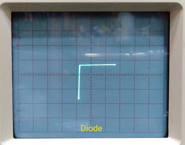


Basically, what’s on the back plugs to XY or channel 1 and 2 on the scope, what's in front plugs to the device under test? Yes! To facilitate good horizontal and vertical display, some tweaking may be needed at each volts per division rotary switch of each channel at the scope. On the Octo-Curve, the left knob is the Vari-Volt for width adjustment (12VAC to 0VAC). The 3 way Vari-Amp selector allows current steps from 1mA, 12mA, 55mA at 12VAC. Apply V=I/R formula when playing with the Vari-Volt. By default it’s wired to 1mA, 12mA and 120mA. I've included two extra unwired current loads inside. Wire it according to requirement... All these tech talks are unexciting so let's debug some common components to see its characteristic on the scope. For this demo I'm using my shifty eyes people’s power GW Instek 20 MHz analogue oscilloscope. Of course, on Digital Oscilloscope is do able also but the display isn't going to be pleasurable nor prompt.


